drawing 3d elements in ansys
My relationship with 3D FEA is definitely dearest and detest. There are things I call up are critical, and those that are completely unnecessary near of the time. Let's take a deeper look into this today!
3D FEA has an advantage: there are things that you simply cannot solve in 2D. But of course, this doesn't mean that 2D FEA is useless… really far from information technology! As well, the answer strongly depends on what y'all hateful by 3D and 2D!
I hope that I sparked your curiosity a bit! Let's start with what it actually means that FEA is 3D or 2nd!
What do 2d and 3D mean in FEA?
This is seemingly a unproblematic question. But to be honest, information technology isn't! I too think that it's pretty important to differentiate this, every bit engineers ofttimes say 2d or 3D FEA while thinking about unlike things!
It all starts in space!
I think that it'south quite obvious that you can have a 2nd and 3D "space" in your model. This means, that you lot will have different "motility and deformation possibilities" in your model. I already wrote a post about the Degrees of Liberty then I won't go into this hither (read this if you lot are interested of grade). More often than not, information technology'southward quite elementary to show the deviation betwixt 2d and 3D "space":

Elements have dimensions besides!
The trouble is with names. Plate elements are often called "2D elements" while solid elements are "3D elements". This makes information technology a chip "funny". After all, yous don't know what someone ways if they say "2D FEA". They may be referring to a 2D space in your model or to the utilize of plate elements. I would say that a decade agone (maybe a scrap more) using 3D space wasn't very common (due to calculating costs). Back then, 2nd FEA almost ever meant "2D space of the model". At present, almost every software operates in 3D space "by default". This ways that "second FEA" more ofttimes refers to plate elements! You can learn more almost Finite Element Types in this mail service!
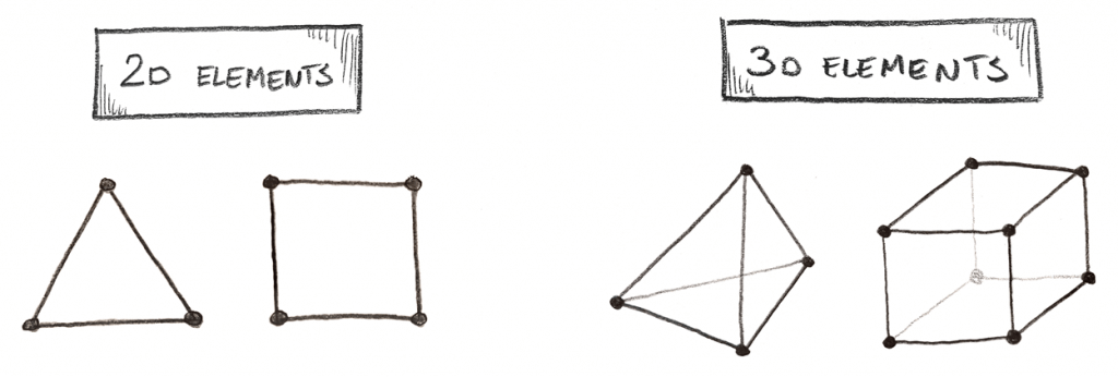
Thanks to a kind annotate by David Oliviera on Linkedin I realized, that I've missed something. When I will be discussing 2D elements, I'm referring to aeroplane stress elements. It'southward as well possible to have plane strain elements (where the length of the model is "long" and "constant" and nosotros are analyzing a "section" of the problem). Somehow I've missed that while writing the post!
Mixing it up!
This gets quite ridiculous when you try to mix the above. In 3D it'due south even ok since you need a 3D space to do 3D elements. But you tin use 2D elements in a 3D space… is this 2D or 3D FEA and then? Autonomously from obvious (2.5D!) I won't even try to answer that, as I hate arguments about semantics!
Merely this is a serious thing, equally, in the end, we volition have to define what nosotros are even talking most! This is why I've made all the "reasonable possibilities" listed below, divided past element types. I will refer to space as 2D and 3D, and I volition call elements plates/shells (for 2D elements) and solid elements (for 3D elements) to avert confusion!
I omitted 1D space since I don't retrieve it is used at all 🙂
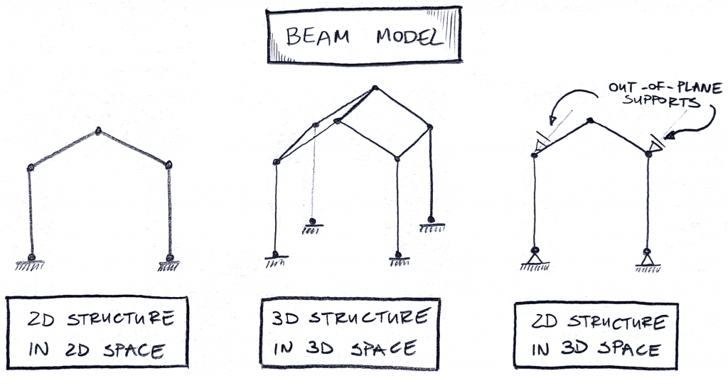
Information technology'due south good to see, that while beams are technically a "1D element" its super easy to brand a second or a 3D model from them. This is the "infinite" component that I've described above. Simply put you need to have a 3D space in your model to "build" a 3D structure from beams.
Simply in that location is likewise one more thing. If you make a second structure (a unmarried frame above) notice that information technology's not the aforementioned in 2d and 3D space. You don't have to support the frame in the "out of aeroplane" direction in second space. Simply put… at that place is no "out of airplane" direction in 2d!
But if you copy the same model into a 3D space, suddenly it's unstable… because information technology tin "fall downward" in the "out of aeroplane" management. This is why a 2nd structure in a 3D space needs additional "out of aeroplane" supports marked to a higher place! Nosotros will hash out the differences in a 2nd!
Just permit'southward finish with all the possibilities ok? Next, are the plate/shell elements:
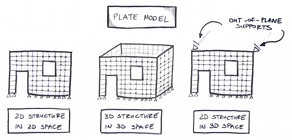
Every bit you can come across, it's the same as in the instance of beams. I can do both a 2nd and a 3D structure from my plate/vanquish elements. And if I have a second structure in a 3D infinite I still demand to worry about out of plane supports.
And finally solid elements… not much to say here, since they demand a 3D space to "be". This means in that location is really only ane choice:
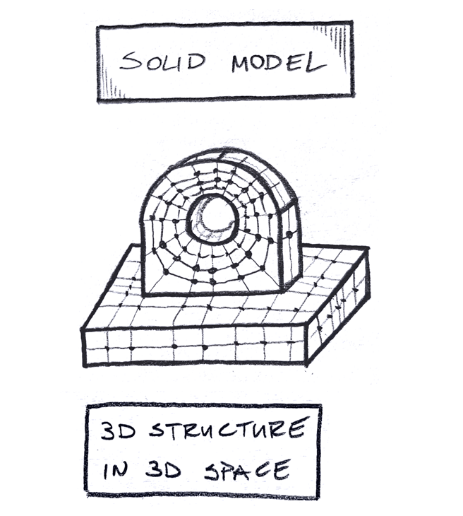
All right! It seems similar nosotros know what we are talking most now, and then permit'south compare the 2d and 3D possibilities shall nosotros? I volition start with the "space"!
second vs 3D "infinite" in FEA models
This is a good starting point. After all, one of the first things you accept to decide, is whether you desire to use a 2d or 3D space in your FEA model.
I get the feeling that several years ago, this choice was well-nigh calculating time (3D models are usually bigger and so they compute longer). At present, it'southward more most the time yous need to prepare things upwards (2d models are usually faster to brand).
2nd "space" is only put "flat". Something similar the examples below:
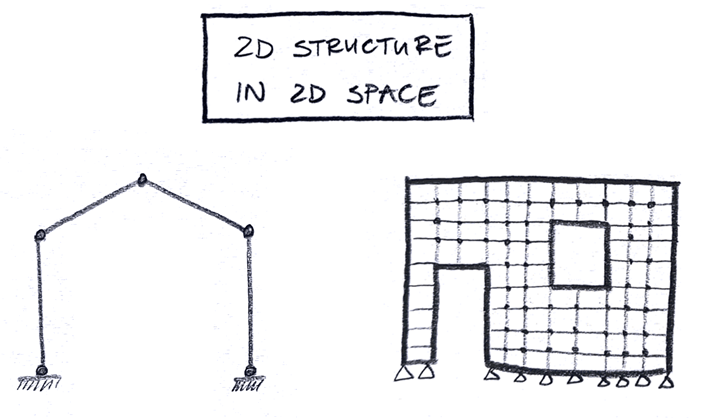
I always felt that 2D "infinite" models are missing things. But this doesn't mean that they have simply negative sides. Let'due south get-go with the positives then:
2D "space" positives:
The biggest positive (and I guess drawback at the aforementioned fourth dimension!) is the lack of 3rd dimension. You don't have to worry about supporting your model in the out-of-plane direction… since there is no such direction!
Also, there is less Degrees of Freedom to "consieder" in FEA, so the models will run faster (you can read more near DoF in this post!). I must confess that it's difficult to imagine a model in 2nd where computing would exist a big issue (those are usually quite modest to be honest). But, if you happen to have a "huge" model, that is totally flat… and then this makes sense I guess!
I think that at this point y'all already know what the biggest drawback of a 2D space is… and of course, it'due south the lack of the 3rd dimension! Usually, this is associated with the fact, that you cannot build a "existent" 3D model. The difference is:

This is, of course, truthful, just I think that the real drawbacks lay elsewhere. It all comes downwardly to accuracy (as always), and the amount of needed work!
second "infinite" negatives:
It's pretty like shooting fish in a barrel to "forget" that y'all accept a 2D model. For instance, when yous analyze buckling in a 2nd frame… nothing will buckle in the out-of-plane direction. Simply put, there isn't such a direction in your model! BUT! In reality stuff can easily buckle this style. This shuold exist analyzed of course, simply your model cannot do that!
While in 2nd you lot don't have to worry about those out-of-aeroplane supports it'southward not all the aforementioned where they are in reality! It's very easy to forget about such problems while solving 2nd models!
Simply there is too question of how your model works. This is also easy to miss, but to explicate that I will need an instance!
My model in 2nd and 3D "infinite"
There is something about your model that is sometimes called "spatial piece of work". In essence, you can try to simplify a 3D model into a selection of 2D bug, but it's not always easy!
The best examples come from beam models, but this goes to plate models likewise of course (yous can't have solid models in second, then they are out of the comparing for now). Allow's utilise a relatively simple steel hall building as an example.
If the situation is simple, things are unproblematic:

Sure, you lot should be a fleck careful about how you load a 2D model. Usually yous would apply the loads on the roof to the purlins, and those would load the roof rafter (in a 3D model). Still, in 2D you don't take the purlins, so information technology's reasonable to load the rafters with loads applied where the purlins volition exist attached. This is a small effect, of course!
The bigger problem comes, when something makes things "uneven". Imagine, that your hall edifice has five of those 2d frames (so information technology'south long). Just, in the middle frame, we accept to remove the heart column (for whatsoever reason). I did a schematic to show what I mean – notice that the isometry is only the "left half" of the building and truss is actually in the centre (at that place is an identical right side, and a middle wall is a symmetry plane):
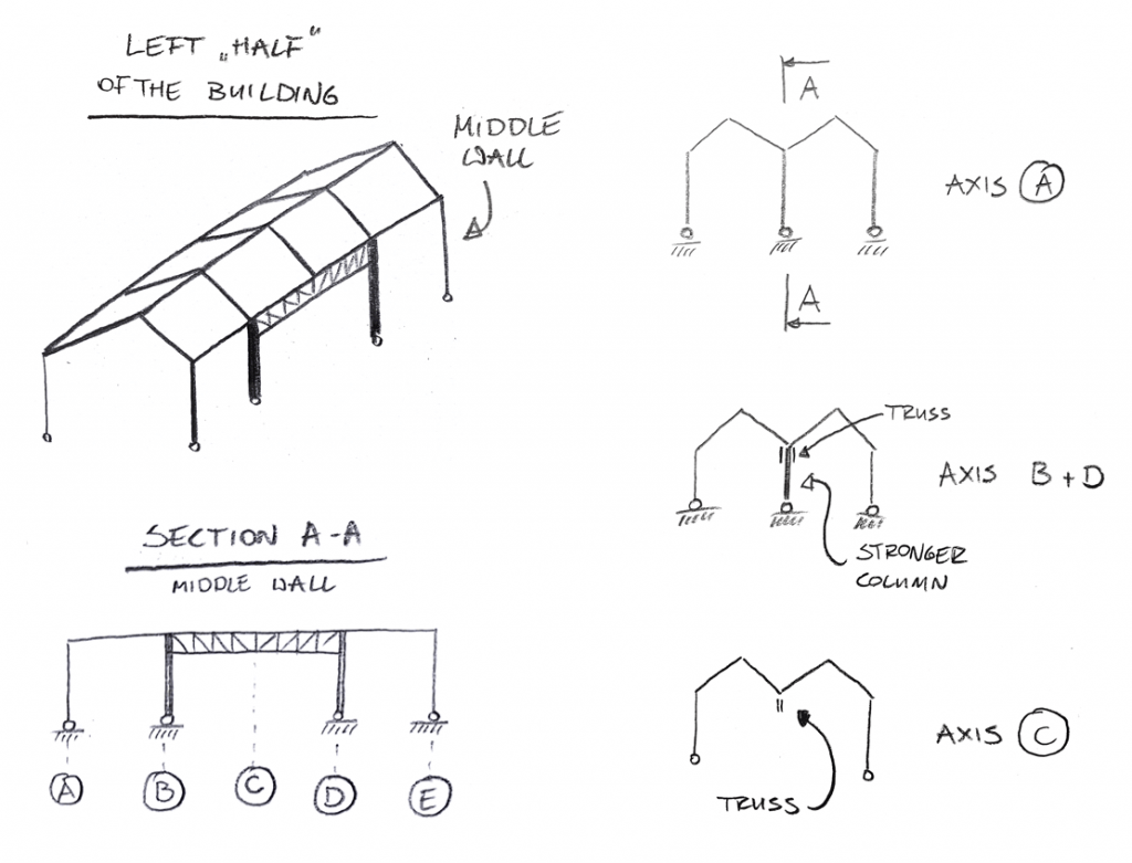
If someone would ask united states to pattern this, but with a 2D model, information technology's instantly clear that nosotros need several of those 2D models right?
I can imagine that the procedure would look similar this:
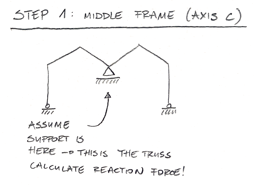
Firstly, nosotros accept to estimate the load on the truss. To do that, we can solve the frame in centrality C, assuming that the truss is the back up. Reaction forces on this support will be the load on our truss. Having the load, we can solve the truss:
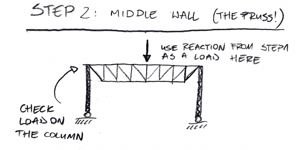
Notice, that I had to cheat a flake. I've made a truss that is continued without a moment connexion to the cavalcade (the original sketch had a rigid connectedness). Since I will analyze the "flat 2nd frame" next, at that place would be no way to employ the angle moment in a perpendicular plane… it seems we are already striking on problems!
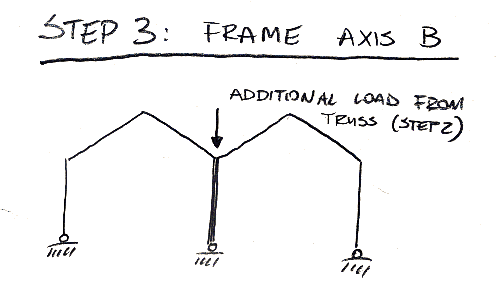
Finally, having the load from the truss (no perpendicular bending moment!) I can brand the Frame in Centrality B, and calculate the "stronger column" I need there. And that would exist it.
Modeling in 2D space:
As y'all can see, to apply 2nd modeling effectively you take to understand how things piece of work. And this is a expert thing! Definitely 2nd modelin teaches you how structures work, and it's awesome!
Is this less work than modeling the whole edifice? I would say that at this signal… yup! Sure, nosotros had to do several different models, but they were pretty like shooting fish in a barrel to make. Also yous become a chance to really understand how your models work this way!
We ran into some troubles through. If y'all will accept elements that are bended out of plane (i.e. bended in two directions), you are done! There is zip yous can do well-nigh that in second.
… just this is non all. In that location is a cruel twist hither!
The barbarous twist with 2D geometry!
I must admit, that I cheated you a flake, and I actually hope that yous've noticed it. If y'all did, so you tin can easily build 2D models! Merely I get a feeling that you lot also know, that it's more work than reasonable in such cases!
I sneaked a really ugly assumption to the previous procedure. If y'all don't know what was it, stop reading and go dorsum and effort to find information technology! I'll wait here for you to come back 🙂

Ready?
All right!
In *Footstep ane* I causeless that the truss is the vertical support. This is hardly the case! In reality, the truss deforms under the load. This ways that in *Step 1* I shouldn't presume vertical back up. Instead, this is a bound in reality… and I don't know the rigidity of that spring!
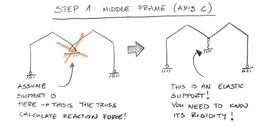
Of form, I could calculate the rigidity of the leap, but I would have to know the solution of the truss outset. And this becomes iterative to some degree! The more truss deforms, the less rigid the spring. The less rigid the spring, the less load it will "accept", and the truss volition deform less. Not to mention that I demand to start somewhere anyway… and in the first iteration, I would assume the rigid support! It just shouldn't be the end of the calculations!
But this is merely role of the point! The bigger part is, that the roof rafters would accept much worse working conditions in the middle frame (axis C)! This is because the middle back up isn't too rigid! This would mean that bending moments in the roof rafters would increase. Something nosotros would completely miss in our procedure!
This is one of the good examples of support rigidity. If you want to larn more about it, definitely sign upward for my complimentary FEA course here.
Limitations of 2nd space
I think that the to a higher place example nicely shows the limitations of second space. Whenever you try to employ 2nd modeling, you only assume that you volition exist able to accurately correspond what is happening in the "other directions" of your model. This doesn't have to be a bad matter! Permit's take a look at the pros and cons:

If you know how to represent "the missing dimension" accurately – 2D is your friend! Of course, if the problem is relatively simple – then in that location is no issue with this at all! In either case, 2nd modeling tin can actually be fast and effective. Furthermore, it gives a sure understanding of how the model really works – and this is a adept thing for sure.
I strongly believe that information technology'south good to model some things in such 2d schematics equally I did here. Information technology actually teaches you lot how structures behave, and why. This is definitely an important skill to have!
In some cases, computing may exist an issue. Without a dubiousness, 2D models will compute much faster. I'm not certain however if this is a real effect nowadays!

Did y'all notice that for more complex cases 2d modeling reward depended on your skills? If you did find what I cheated on in my example, you should be fine. Simply if you didn't? Yup… 2D modeling forces you to brand a LOT of assumptions. Non all of them are crystal articulate all the time.
It's only easy to miss that something is a bound, non rigid support, or that there will exist torsion involved, or bending in the second management, etc. In other words, information technology'southward best to be careful and constantly recall about how things piece of work! 2D modeling isn't as simple as engineers recall! In some sense, information technology's more difficult than 3D modeling!
It'southward too pretty easy to forget that in 2D… you really do not have the 3rd direction. So there will be no buckling nor vibrations in the out-of-plane! This tin lead to problems if y'all won't realize this in time! This is why it's often a good idea to model a second trouble in a 3D infinite… just so the elements can really buckle in the out-of-plane direction! This, of course, forces y'all to consider, where your 2nd model is supported in the out-of-airplane direction (and if the support is a spring!). This is why I showed you lot 2D models in 3D space before:

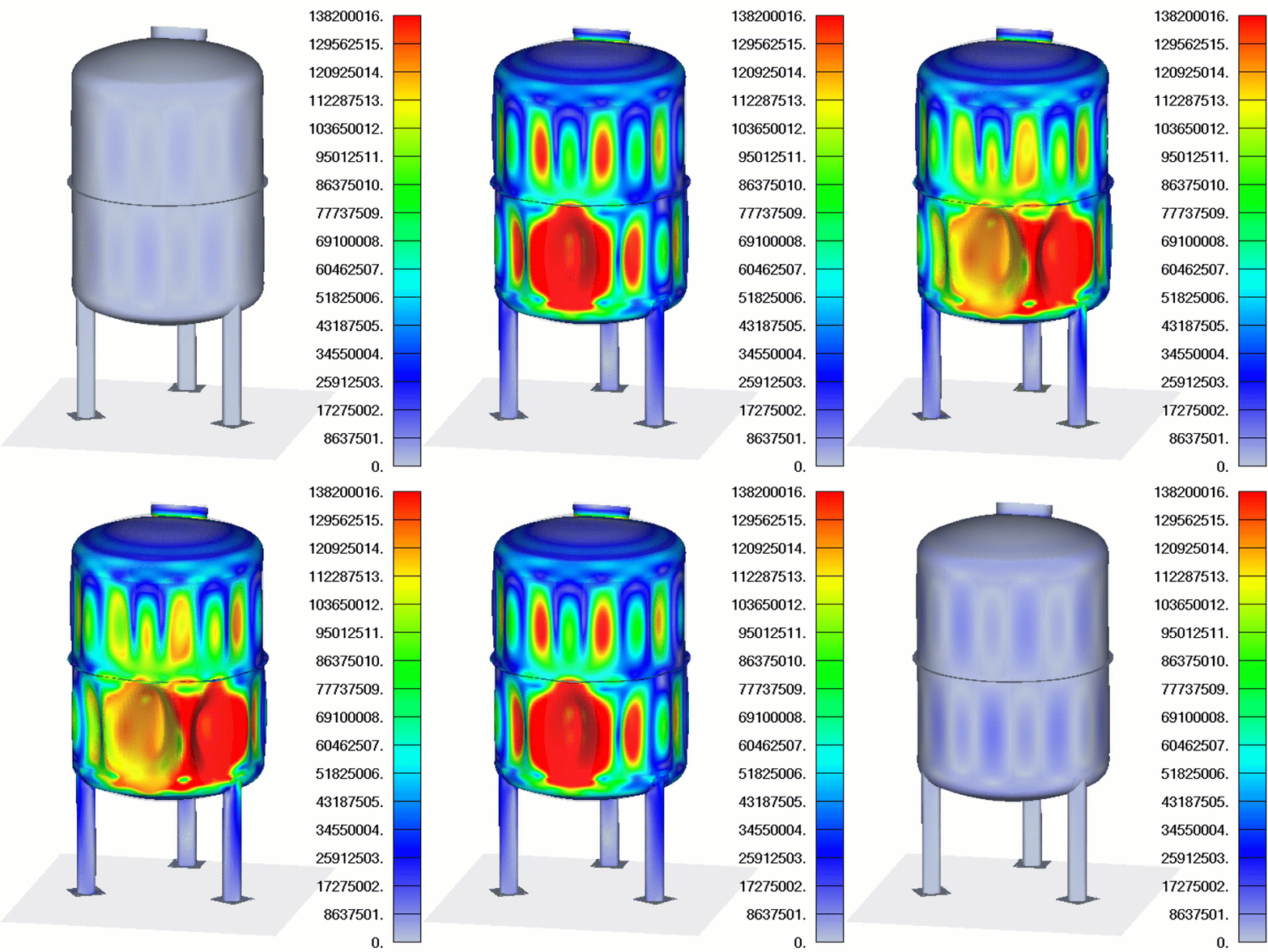
Of course, there are things yous simply can't model in 2d. But in those instances, you don't take a choice, so I estimate that there is no point to discuss that! If you really need an example, try to model and summate this in 2D:
3D space!
I think that everything is clear, simply I want to drive the betoken dwelling! Allow's take a look at the pros and cons of a 3D infinite!

3D space solves most of the in a higher place problems "automatically". If I would model my hall building with the truss, I wouldn't have to worry most the leap stiffness. The solver would "automatically" know, what is the rigidity of the construction, and act accordingly (no iterations needed besides!).
I can't also make some "stupid" assumptions nigh out-of-plane supports etc. Since I have all the elements in my model, their rigidity volition be taken into business relationship. I don't have to assume anything.
Also, there are issues you lot can solve only in a 3D space… so this is an obvious advantage as well!

But of course, it'south not all sunshine and rainbows!
3D space is a fourth dimension hog! It takes significantly more than time to build all the models. It'south also easier to brand modeling mistakes (and much harder to find them)!
But in that location is also something else… if you build a huge model, you lose "contact" with information technology! The bigger the thing, the more than distant information technology becomes. It'southward so easy to "go lost" in your huge model. And sometimes you will simply "believe" that everything is fine (even though you've literally "lost command" on what is going on in the model). This is a pretty unsafe thing!
A 3D model can "find" something for you (like the truss rigidity impact on the outcomes). Yous tin literally correctly take into account effects y'all had no thought that they exist! But this is a double border sword, as information technology's also piece of cake to believe your "big and smart" 3D model… likewise when information technology's completely incorrect! And finding why it's wrong will be much more hard than in the case of 2D models!
2nd vs 3D elements in FEA
This is the second part of the word! So far we have covered the "infinite" aspect of the 2nd vs 3D! But of course, there is all the same the element role we need to dig into.
This may seem like the "more hard" part of the problem, but information technology's actually much less complex! In the infinite, we had to deal with assumptions, what we lose in 2D, and talk over second elements in 3D space and all that.
Here, we simply have to compare 2D and 3D elements!
While this is much less complex, I think that this aspect causes A LOT of confusion and errors!
In fact, I recollect that using 3D mesh where 2D mesh should be used may be the most common FEA mistake out there!
3D elements and their uses
If I had to guess I would say that 3D elements are the nigh common elements in FEA. There are many situations where using whatsoever other element type only won't work.
In very short, no affair how hard you endeavor, you won't be able to model this using 1D or 2d mesh:
The problem with 3D mesh is… that literally everything can be meshed with 3D…
I would never argue against using 3D elements when they are needed. But I know that those elements are greatly overused! In my Breakthrough FEA course, I refer to 3D mesh every bit the "mesh of terminal resort". What I mean is, that you should use 3D elements, only if using 2d elements is not possible. In that location is a good reason for this, trust me!
The reality is, that 3D mesh is used wrongly in a tremendous amount of cases… because of CAD geometry! Every time I go a model from a Customer as an input, it is done as a 3D .stp or .parasolid file. This ways, that each plate has a modeled thickness! It's only natural to mesh something like that with 3D mesh… the model is practically prepared for it:
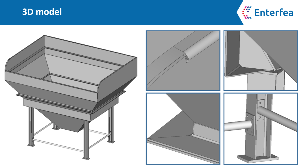
As you tin see above, there are a few places where the model should be simplified, just apart from that geometry is fix for a 3D mesh…
And that is an event, as in this particular case 3D elements will only hurt you! What should be done instead is preparing a "2d geometry", or to be more precise a geometry fix for a second mesh. Information technology's actually quite some piece of work! To the bespeak that in many cases we started doing models "from scratch" in 2D instead of using 3D models… as de-featuring would take longer than creating the 2d model!
Whether you take the de-featuring route, or y'all start the plate model from scratch, finally, it would expect like the one beneath (notice that each plate does non have a thickness, and all are connected in "corners"):
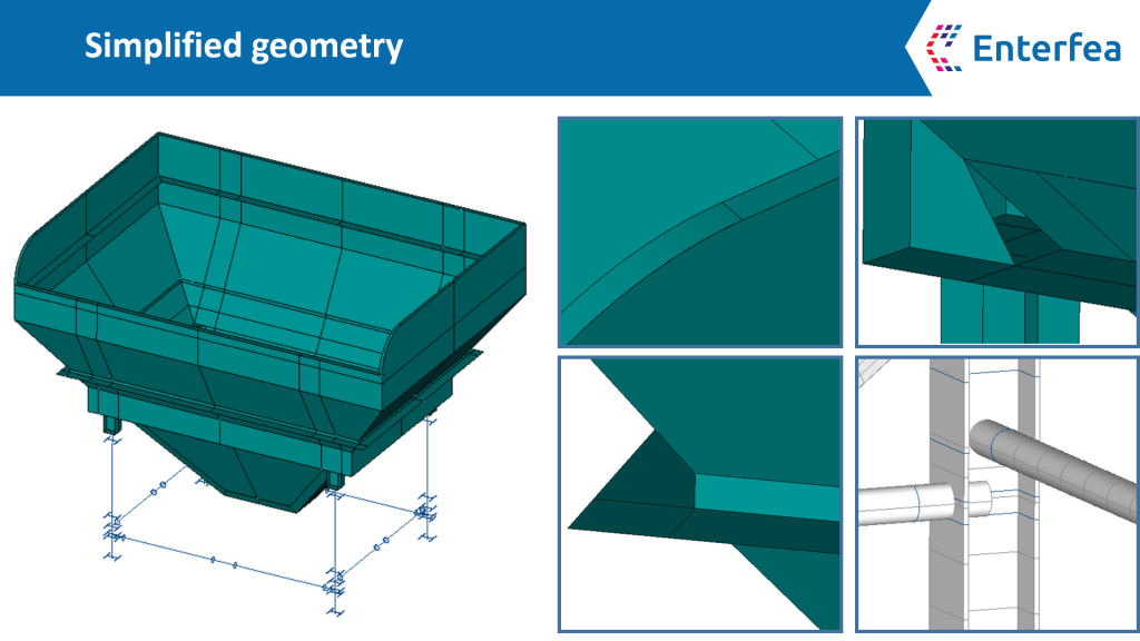
Information technology took us a few hours to prepare the model above… It's no wonder why people don't want to do it… it'south time-consuming, and everything nowadays has to exist done and then fast!
The matter is, that every hour you put into that, y'all will become back in the accuracy of outcomes and analysis time!
Plates/shells don't like 3D elements!
Wait, what?! Accuracy of outcomes is lower with 3D elements?
Merely I've heard that 3D elements are the most accurate bunch since simply they can represent the geometry accurately!
I retrieve the above is the most typical response to what I just wrote at the end of the last section. And this is a sound argument we should deal with, to move through the topic.
The thing is, that in social club to make 3D mesh to piece of work, yous need a LOT of elements. Mostly, considering the 3D mesh was non created to model plates and shells (this is what 2d mesh is for!).
Only put, to capture angle properly, you need several elements through-thickness of your plate/shell. While this may not sound like a big trouble, it's very easy to create a model with millions of elements… particularly since you want to avoid HEX elements with poor attribute ratios:
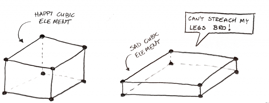
You apace start to realize, that plate structures (like the hopper above) just cannot exist done properly with 3D FEA… in a reasonable time!
And that is the principal thing! Information technology's not that you cannot properly calculate a plate construction with a 3D mesh… you tin can! Merely, it will take ages! You will take to spend a lot of time waiting for calculating to end – non the best tradeoff!
What to do nearly it?
All, right! Information technology's all overnice, but permit's wrap the 2d vs 3D Elements thing into one actionable rule:
2D vs 3D Elements!
If it is possible to reasonably model the element yous analyze into 2nd shell/plate model… this should be done!
3D elements should be reserved to solve issues that cannot be hands simplified to 1D or 2nd element geometry (beams and plates/shells).
This is not just to save computing time. Using too few 3D elements (like 1 per plate thickness etc.) can really reduce accuracy of your analysis!
Summary!
Permit's take a last look at what we covered here today:
- 2nd infinite in FEA models isn't bad. Notwithstanding, it's expert to exist aware of all the assumptions you lot need to do to build such a model (similar in the truss example). Using 2nd tin actually assistance you to understand how structures work.
- 3D space in FEA models allows us to automatically have rigidity of everything that is modeled into account. There is no need to assume spring stiffnesses and iterate those… model will practice it for yous! The problem is, that 3D models tend to be pretty big, and information technology's like shooting fish in a barrel to "get lost" in them. This may hateful that y'all are analyzing a model only you don't understand how it actually works. This isn't the best idea 🙂
- 2D and 3D elements are pretty easy to compare… You lot should always utilise 2D elements when possible, treating 3D mesh every bit the "last resort" solution. In that location are of form a LOT of models that can only be done in the 3D mesh. But when you utilise 3D mesh where 2D elements would exist better at animate being you lose a lot of calculating time, and at worst you damage analysis accuracy.
Thanks for reading! I really hope that you lot like the commodity, and of grade please share your thoughts in the comments below 🙂
Want to acquire more?
This is awesome! I've prepared a special free FEA course for my subscribers. Y'all tin get it below.
Source: https://enterfea.com/2d-vs-3d-finite-element-analysis/
0 Response to "drawing 3d elements in ansys"
Post a Comment